What is a patchbay?
A question many of the newer generation of audio engineers may be asking is: “What is a patchbay?” Since a lot of work these days gets done completely inside the computer environment, a patchbay is not always necessary and is sometimes not included in the modern workstation. In this installment, we will answer the question: “What is a patchbay?”
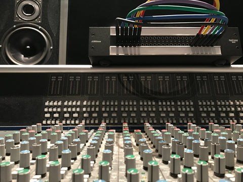
A patchbay is a group of up to 96 individual audio (or video) connections that allow you to configure the signal path in your studio in any order you wish. Using a standardized connector, (either ¼” TRS or TT formats) one may take a microphone signal that originates in a remote part of your recording space and route it to any mic preamp, then to a compressor, then an EQ, then to a recording medium or any other possible destination for processing. Patchbays bring all of our possible signal paths to one convenient location so we can decide, (depending on our own individual needs at a particular time) how to route our signals.
What is a patchbay? There are many types of patchbays and they are all not created equally. Regarding audio patchbays, there are RCA, TRS and TT. RCA patchbays are only useful if you are dealing solely with unbalanced audio signals such as those on consumer tape decks, CD players and other consumer equipment. Occasionally a professional deck will have both balanced and unbalanced connections, in which case you would usually want to use the balanced connections, but we will touch on this later. Balanced signals are not compatible with unbalanced patchbays such as RCA patchbays so if all of your signals are unbalanced, you can use an RCA configuration. If any of your signals are balanced, you need a balanced patchbay such as a TRS ¼” or a TT bay. Most RCA patchbays have RCA connectors on the rear to get your signals in and out, and RCA on the front to do your signal routing.
¼” TRS bays are very common and have quite a bit of usefulness in today’s studios. They utilize the standard ¼” size connector that most all pro musical equipment also utilizes. Generally they come in a 2x24 configuration, which consists of two rows of 24 jacks each. The TRS stands for Tip, Ring, Sleeve and corresponds to the signal hot, signal cold and the ground signal paths inside the cable. Don’t mistake the guitar cord (TS ¼”) for a TRS cable- they are very different. TS cables are for sending strictly unbalanced signals and TRS cables can carry both. If you are using a TRS patchbay, make sure your patch cables are all TRS cables to insure you are transporting only balanced signals and to make sure you are not introducing unnecessary noise. Typically your signals will physically plug into the back of the bay with a standard ¼” cable and then your signal routing will be done on the front with the same type of cable.
The pro level and certainly most configurable type of patchbay is the TT bay. This is the type of patchbay that most professional recording studios, television stations, and post production facilities employ. They are configured in 2x24, 2x48 and occasionally other configurations but 2x48 is the most common. Most manufacturers of TT bays allow for some type of internal signal routing that is meant to save you time in the studio and allow for maximum flexibility when using your studio. These can include automatic normalling connections that take a favorite output and route it to a favorite input. Internal connections can be made to group the grounds of several signals together or to isolate them from each other. Signal paths can be made to connect always or half of the time depending on whether there is a patch cord inserted. The TT bay can have any number of single channel or multi channel connectors on the back to get your signals in and out, but will always have the TT or Tiny Telephone connector on the front to do your signal routing.
So what is patchbay? A patchbay is a very handy piece of equipment that can be configured in many different ways to allow the signals you rely on in your studio to be where you need them when you need them. If you have outboard equipment or a recording console in your studio, it’s highly likely that you need one.
The RJ45 Pinout
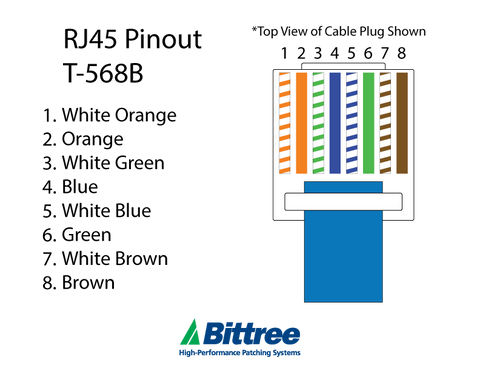
The RJ 45 pinout is a result of the TIA standardization of cabling between commercial buildings. Many telecommunications, data, audio and other industries have adopted this protocol.
Click here to buy a RJ45 connector from Amazon.
The EIA/TIA and over 60 additional organizations contributed to this new standard. Terminated in the RJ45 connector, the 100-ohm, 8 conductor twisted pair cable known to many as Ethernet, is now ubiquitous. What is formerly a data or telecom related cable/connector is now in use worldwide to stream HD video, interface with security cameras, transmit audio, and send low voltage power, sometimes a mixture of signals and power. Many devices convert the signal at the transmit end to a different format, send the information then decode it again at the other end to gain certain advantages for the device. The RJ45 connector and standard RJ45 pinout are used in many ways in today’s technology. Other devices utilize the telecommunications standards to send data between two or more devices, such as computer Ethernet ports, which are bi-directional. The RJ45 and its pinout have become a common sight in almost every aspect of our lives.
Many companies spanning several industries adopted the new cabling standard terminating in an RJ45 connector leading to vastly more people familiarizing themselves with the format and the standards. Orange white/Orange, Green white/Blue, Blue white/Green, Brown white/Brown is the common color code for this connectors This code, used for RJ45 connectors is called the 568B RJ45 pinout standard and is used throughout the Telecom and AV industries today.
The reason why the RJ45 pinout is the way it is relates to crosstalk. When the conductors are paired up and twisted, they naturally resist crosstalk from signals in the other pairs. From one end to the other, the pairs inside must be twisted at different amounts and this tolerance has to extend all the way to the ends of the cable in order to take full advantage of the phenomenon. The RJ45 pinout is a reflection of the science behind the standard
As the years move forward and technology avails new options, new innovations will be driven and developed which may require new formats and new standards. For now, the RJ45 connector and its familiar RJ45 pinout will be our mainstay.
Tech Addendum
As it relates to the integrity of the cable and the connectors, there are some methods you want to always practice when handling and installing twisted pair cable so the infrastructure supporting your signal path is at maximum integrity.
Bend Radius:
CAT 5-6-7 permanent installation cable that is of high quality will have solid conductors and thus cannot be kinked or too sharply bent as the solid conductors within the jacket will weaken with each successive excess bend. Always handle the cable without exerting excess force on it. If an end of a cable that was determined to be kinked or damaged, its slack should be cut to ensure a faulty cable does not get terminated.
Termination:
When using standard RJ45 connectors, it is important to prep the cable then visually inspect it one final time before you apply the crimper. This way is you do not have the conductors all in a position for a 100% good connection, you can re arrange them before crimping and only crimp the cable one time.
When using the EZ RJ45 connector, one may pull the strands out the end of the connector, pull slightly in opposite directions the connector and the strands and thus capture maximum insulation under the crimp thusly creating a more solid termination. Prior to crimping, twist all 8 conductors together slightly as to create one big scrap cut off. Crimp connector and insure all 8 wires are cut perfectly flush. A small bit of dangling insulation is all that is needed to keep your end from locking into place so make sure the end is free of stragglers!
Have you ever wanted or needed patchbays explained to you? Do you wonder what exactly it is that patchbays do? If you are new to the world of pro audio or pro video or have recently encountered a need for such a device, today you will have your explanation!
A patchbay is a device that groups all of the inputs and outputs of the equipment in your studio into one convenient location and allow maximum flexibility in signal routing. Audio, video and control patchbays do basically the same thing but do so with the appropriate connectors, cable and terminations for each type of signal sent.
Video patchbays explained:
Video patchbays bring together video signals from the outputs of cameras, synchronization devices, signal generators and matrix routers up to a convenient location so you can route them how you see fit. These outputs are usually located on the patchbay in such a way that they will flow from a top row down to a bottom row, which is where the inputs are located. In many cases, it is desirable to have the output row on top and the input row on the bottom. Many patchbays are configured internally so that any output signal present on a top row will automatically flow into the input jack directly below it. This is the normal layout for a patchbay because it saves us from having to physically patch each bit of a signal path by hand. Utilizing the features of the hardware itself saves us from using all of our patch cables up too soon. Audio patchbays do the very same thing that video patchbays do but with some exceptions. With audio, you can route a signal to more than one place without degrading the signal much. With video, this is not possible without electronics to boost the signal before it is split. Video patchbays use either the Weco358 or mini Weco440 type connectors and patch cables.
Audio patchbays explained:
Audio patchbays are similar to video patchbays in that input and output signals are brought up to a convenient location. Top row output jack signals can automatically flow down to the bottom row input jacks internally. Those same signals can be isolated from each other as well. The main difference is in the difference between the types of electricity that constitute audio and video. While audio is robust and can flow through different types of conductors and physical connections on its path, video is much more sensitive and has several special requirements and therefore video cannot be connected to an audio patchbay. Balanced audio consists of electricity that is alternating current with a DC offset. That’s very technical sounding but basically what it means is that audio is not video and audio is not a control protocol. Audio is robust but it is its own format and has its own unique requirements. Audio patchbays come in several types including RCA, ¼” and TT. Most professionals use TT bays but occasionally use a ¼” or possibly an RCA patchbay for certain setups. The ¼” bay is most commonly found in project studios or non-professional setups.
Conclusion: Patchbays are a very helpful part of studio architecture. They bring all of your connections to a single convenient location and allow maximum flexibility.
Do you need to splice together some audio or low voltage contacts or are you debating which connector to get on the back of your new patchbay? Between the easy to manage 2” standard stripped length and the true cross-sectional area maximization, the E3 pins are the superior mating connector. Besides the superior electrical connection provided by the cross, the E3-pins also provide a very robust physical connection to the wire itself, providing both a primary and secondary crimp sequence. Today we’ll talk about how to prep your cable for E3 pin connectors and provide some resources for your next project.
If you are a fan of Bittree’s patchbays, you’re familiar with the E3 pins connection as it’s their standard. If you’ve used some other brand of patchbays in the last 10 or 20 years then you might not have run across this type of termination. Fortunately, they are very easy to use and provide a solid connection ideal for two conductors shielded cable commonly used in recording studios.
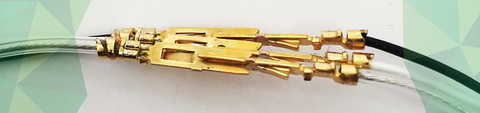
The first thing you want to do when you’re prepping your cable is to strip and confirm the gauge of the drain wire and obtain the proper size of noodles as I like to call them- the pre-cut Teflon tubes. You also want to make sure you have some 1/8” or 3/16” shrink wrap to cover the split. After you’ve stripped your cable back 2 1/8” and you’ve slid the Teflon over the drain wire, make sure it’s seated and heat-shrink the shrink wrap evenly over the insulation and the insulated pair. Now cut all 3 conductors even and strip each one back 1/8”. Your bare wire should end up squarely under the dual crimp contact and the strain relief should wrap around about another 1/8” of the Teflon. See the photo below for a perfect example.
As with any termination, you always want to give a bit of a stress test to each of the pins you crimp. A slight tug ensures that the pin is physically secure. Once this is done on each pin and you’ve done a quality control check, only then should you insert the pins into their designation on the connector. If each pin is crimped perfectly and at the same length, there will not be more stress on one pin than another and the conductors will appear even when stretched out straight. When inserted into the mating connector, they should remain straight and at the same apparent length as well. After all of the physical connections are tested and a quality control check is done, now they can be inserted into the mating connector.
Now that the pins have been put into the mating connector, it’s always a good idea to electrically test your connections from pin to pin to insure the pinout is proper and that you’ve got solid continuity on each conductor. Any multimeter with a continuity setting will do. Use a reference drawing of your mating connector when using E90’s if you need to keep track of each test. Once you’ve tested everything, go ahead and make the audio connections everything should be good to go!
E3 pins are still today’s de facto standard crimp style mating audio pin. Whenever I see a picture of them I appreciate the genius in their design again. An E3 pin or E90 connector properly mated will guarantee a make a solid connection.
Normalling your patchbay Part 3 - GROUNDING
Today we are going to talk about grounding exclusively in the context of normalling your patchbay. There are professionals out there who focus specifically on grounding and command a high price for their services. Here at Bittree we aim to give you an introduction to the world of grounding as it relates to your patchbay.
The ground connections on most pre wired patchbays are all tied together. Each patch point’s shield is shorted to all of the other patch points on that row, what we normally call ‘bussed’. This may or may not be a desirable setup for you, depending on the quality of your studios’ electrical grounding and other factors.
Partly due to the advent of programmable patchbays, much of the problems of ground hums on the bay have been alleviated. Programmable patchbays offer removable shunts that allow the user to configure each patch point’s configuration (isolated, normalled or half normalled) and ground state (isolated, bussed or looped) quickly and easily.
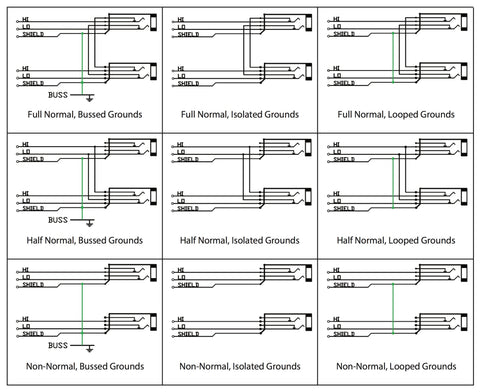
LOOKING AT EACH GROUND CONFIGURATION
SWITCHED
Switched grounds refer to the configuration where each vertical pair of audio circuits has shields common, but isolated from the front panel and adjacent circuits. Same as looped ground, however inserting a patch cable lifts the shield. If your bay is wired this way, on the input side, when you insert a patch cable, you are now using the ground from the new source signal. On the output patch point, you lift the ground from the source side.
ISOLATED
Isolated grounding scheme is where the shield of each circuit is isolated from the front panel and each other. Each patch point has its own ground, totally independent from all others. This configuration is the way to go if you have equipment that is notorious for grounding problems or if your studio is inherently noisy. This setup may present problems for you if you have condenser mics that need phantom power. Lay out your equipment normalling scheme on paper before you decide what configuration each pair of jacks will need before you connect everything.
BUSSED
Patch points with bussed grounds have a common shield, isolated from the front panel and bussed to a ground connector on the rear panel. This rear panel connector or stud will be used to tie the patchbay to a common ground outside of the rack, likely in a star grounding scheme. When you’re sure that your studio has a perfect grounding scheme and you want all of your patch points to share the same ground, you want bussed grounds.
LOOPED
Looped grounds are when each pair of vertical audio circuits has common grounds, but isolated from the front panel and adjacent circuits. This handy configuration is useful when it is necessary to carry the shield from the source equipment all the way through to the destination equipment that is being normalled through the patchbay. Phantom power for instance, comes from a mic pre and travels all the way back to the microphone, opposite from the direction of audio. Without the ground connected all the way through, the condenser mic would not be able to draw 48v from the remotely located mic pre.
Normalling your patchbay Part 2 – HALF NORMALS
Are you unsure whether or not to normal your patchbay? Do you need guidance on when TO and when NOT TO normal patch points? Are you wondering which ones you should isolate? Is the concept of normalling confusing to you? These are questions that studio engineers of all skill levels face and the answer isn't always cut and dry. As with many aspects of studio design, this technical topic draws differing opinions even from seasoned professionals. There are engineers that have hallways full of gold and platinum that don’t know the first thing about how patchbays are configured and others with equal amounts of awards that know as much or more than the head tech at Capitol Records. Today we tackle the topic of half normalling and touch on the subject of grounding as it relates to half normalling. The details on grounding will be done in our final installation of the series. Each of this 3 part series will expose the most basic aspects of normalling and deliver some nuances in patchbay configurations in order to put you on a path to success when designing normalling your patchbay.
So let’s say you have your mic lines coming up on the top row and they normal down into some rad mic preamps you have. You want to send your first mic line (your kick drum mic) to another mic pre at the same time and record both signals. With a half normalled configuration, the signal flows through to the input jack below and by plugging into the top jack you can route that signal to a second destination without using mults. (A mult is a group of patch points all wired together so that one becomes all- a group of four points becomes one input and 3 outputs) This is effectively a Y cable, splitting your mic line signal into 2 signals.
As with all patchbay configuration options, you want to choose the option that fits your needs and fits your workflow. The half normal configuration is handy for mic lines as described in the example above but what if you don’t want the mic line signal to go to two places? You can still employ the half normal configuration and cross patch signals as needed by dead patching the input you don’t want to use. Let’s say you’re patching mic line 1 over to mic pre input 4 and you don’t want mic line 1 to feed mic pre 1 anymore. Simply patch an available patch cord into mic pre 1 input and the signal is broken. In the studio the dead patch is an old patch cord end that has been cut off. When a patch cord becomes intermittent, we would cut the ends off and save them for use as dead patches. If you find that setting up your bay half normalled will lead to using a ton of dead patches, half normalling might not be right for you-probably better to go fully normalled when normalling your patchbay.
Normalling your patchbay Part 1 of 3 - FULL NORMALS OR NO NORMALS
Are you unsure whether or not to normal your patchbay? Do you need guidance on when TO and when NOT TO normal patch points? Are you wondering which ones you should isolate? Is the concept of normalling itself confusing you? These are questions that studio engineers of all skill levels face and the answers are not always cut and dry. As with many aspects of studio design, this technical topic draws differing opinions even from seasoned professionals. There are engineers that have hallways full of gold and platinum that don’t know the first thing about how patchbays are configured and others with equal amounts of awards that know as much or more than the head tech at Capitol Records. Today we will tackle the topic of normalling and touch on the subject of grounding as it relates to normalling. This is a 3 part series focusing on normalling (full normalling), half normalling and grounding respectively. The details on grounding will be done in part 3. Each part of the series will expose the most basic aspects of normalling and deliver some nuances in patchbay configurations in order to put you on a path to success when designing and normalling your patchbay
NO NORMALS (ISOLATED)
First, when we discuss a Normalling your patchbay, we are talking about the relationship between a top row patch point and the bottom row point directly below it. A patchbay with no normals is the most simple of all patchbay configurations. This is a completely isolated layout and involves absolutely no connection whatever between patch points (see ISOLATED, Figure 1 below). An example of why you would want patch points to be isolated would be if you had signals on your patchbay that were coming from different rooms of a facility that were on different electrical grounds. Having signal grounds that originate from differently grounded equipment around a facility all landing on one patchbay and tied together might create a maelstrom of ground noise. By keeping them all separate, you keep any ground noise on one line from leaking into all the others. There are other examples, such as the case where you have a cramped patchbay layout and inputs have ended up on both the top and bottom rows (time to buy an additional bay and expand!). Another example is when you have outboard gear landing on a bay that you do not want interacting with anything else in your studio. Keeping all points isolated minimizes any possible interaction between that gear and your other gear unless you physically make the connection with a patch cord.
NORMALLED (ALSO CALLED FULL NORMAL)
Normalling, (also referred to as fully normalled) is the most common configuration for audio patchbays. Let’s start with the definition of normalling: A normalled patch point is one where the signal at the top jack flows through to the jack directly below, making a connection inside the patch bay without the need for a patch cord connecting the two together. A benefit of normalling is to have the bay route signals for us automatically. Example: A line output signal on the top row flows from top to bottom and into a line input on the bottom row without the need for a patch cable. Fully normalled jacks allow the signal at either the top or bottom patch points to be broken by patching into either row. Say you have a mic line on the top row and a mic preamp input normalled right below it. For some reason, that mic preamp is acting up, and you want to patch it over to another mic pre. A fully normalled patch point will allow you to re route mic line 1 over to mic input 2 breaking both the normal signal input to mic pre #2 and the normal connection to the first mic preamp.
If we needed to patch each thing we wanted to route in the studio, we would need literally hundreds of patch cords, creating an instant mess, so anything we can do to limit the number of cords needed to reach a given configuration is best. When you plug in a patch cord to either the top row or the bottom row of a fully normalled patch point, you break the connection between the two points. By plugging into the top jack, the signal to the bottom jack is broken and if you patch into the bottom jack, the signal from the top jack is broken. This is called a full-normalled configuration and it allows you to crosspatch outputs to alternate inputs as the need arises. If any of this is confusing to you, or if you are more of a visual person, refer to the graphic below, FULL NORMAL. See the connections that go from the top jack to the bottom? When a plug is inserted into the jack, the checkmark shaped connections physically move up, decoupling them from those little arrow shaped connections. The same action happens when you plug into the bottom jack and this is how full normalling works!
As you can see in the graphic above, the lines representing the signals for tip, ring and sleeve (T=Tip=hot=pin 2, R=Ring=cold=pin 3, S=Shield=ground=pin 1) are connected to the metal contacts inside the bay that make the physical connection to the patch cords when inserted. When the configuration is fully normalled, the signal present at the top always flows through to the bottom jack AND when you patch into the top jack, you can route the signal to a second destination, allowing it to also flow to the bottom jack.