Posted in Normalling-your-patchbay-grounding
Normalling your patchbay Part 3 - GROUNDING
Today we are going to talk about grounding exclusively in the context of normalling your patchbay. There are professionals out there who focus specifically on grounding and command a high price for their services. Here at Bittree we aim to give you an introduction to the world of grounding as it relates to your patchbay.
The ground connections on most pre wired patchbays are all tied together. Each patch point’s shield is shorted to all of the other patch points on that row, what we normally call ‘bussed’. This may or may not be a desirable setup for you, depending on the quality of your studios’ electrical grounding and other factors.
Partly due to the advent of programmable patchbays, much of the problems of ground hums on the bay have been alleviated. Programmable patchbays offer removable shunts that allow the user to configure each patch point’s configuration (isolated, normalled or half normalled) and ground state (isolated, bussed or looped) quickly and easily.
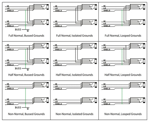
LOOKING AT EACH GROUND CONFIGURATION
SWITCHED
Switched grounds refer to the configuration where each vertical pair of audio circuits has shields common, but isolated from the front panel and adjacent circuits. Same as looped ground, however inserting a patch cable lifts the shield. If your bay is wired this way, on the input side, when you insert a patch cable, you are now using the ground from the new source signal. On the output patch point, you lift the ground from the source side.
ISOLATED
Isolated grounding scheme is where the shield of each circuit is isolated from the front panel and each other. Each patch point has its own ground, totally independent from all others. This configuration is the way to go if you have equipment that is notorious for grounding problems or if your studio is inherently noisy. This setup may present problems for you if you have condenser mics that need phantom power. Lay out your equipment normalling scheme on paper before you decide what configuration each pair of jacks will need before you connect everything.
BUSSED
Patch points with bussed grounds have a common shield, isolated from the front panel and bussed to a ground connector on the rear panel. This rear panel connector or stud will be used to tie the patchbay to a common ground outside of the rack, likely in a star grounding scheme. When you’re sure that your studio has a perfect grounding scheme and you want all of your patch points to share the same ground, you want bussed grounds.
LOOPED
Looped grounds are when each pair of vertical audio circuits has common grounds, but isolated from the front panel and adjacent circuits. This handy configuration is useful when it is necessary to carry the shield from the source equipment all the way through to the destination equipment that is being normalled through the patchbay. Phantom power for instance, comes from a mic pre and travels all the way back to the microphone, opposite from the direction of audio. Without the ground connected all the way through, the condenser mic would not be able to draw 48v from the remotely located mic pre.

Subscribe to our newsletter and always be the first to hear about what is happening.
© 2026 Bittree
Jack Field
Author