Normalling your patchbay Part 1 of 3 - FULL NORMALS OR NO NORMALS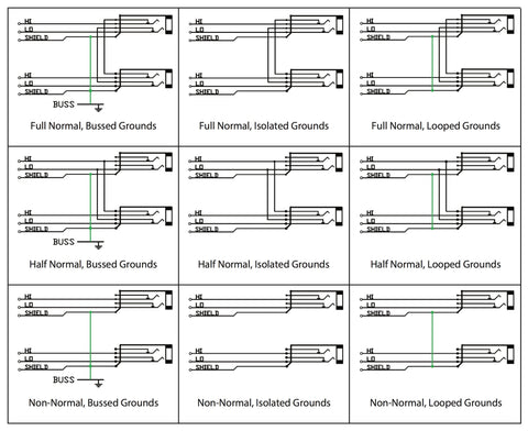
Are you unsure whether or not to normal your patchbay? Do you need guidance on when TO and when NOT TO normal patch points? Are you wondering which ones you should isolate? Is the concept of normalling itself confusing you? These are questions that studio engineers of all skill levels face and the answers are not always cut and dry. As with many aspects of studio design, this technical topic draws differing opinions even from seasoned professionals. There are engineers that have hallways full of gold and platinum that don’t know the first thing about how patchbays are configured and others with equal amounts of awards that know as much or more than the head tech at Capitol Records. Today we will tackle the topic of normalling and touch on the subject of grounding as it relates to normalling. This is a 3 part series focusing on normalling (full normalling), half normalling and grounding respectively. The details on grounding will be done in part 3. Each part of the series will expose the most basic aspects of normalling and deliver some nuances in patchbay configurations in order to put you on a path to success when designing and normalling your patchbay
NO NORMALS (ISOLATED)
First, when we discuss a Normalling your patchbay, we are talking about the relationship between a top row patch point and the bottom row point directly below it. A patchbay with no normals is the most simple of all patchbay configurations. This is a completely isolated layout and involves absolutely no connection whatever between patch points (see ISOLATED, Figure 1 below). An example of why you would want patch points to be isolated would be if you had signals on your patchbay that were coming from different rooms of a facility that were on different electrical grounds. Having signal grounds that originate from differently grounded equipment around a facility all landing on one patchbay and tied together might create a maelstrom of ground noise. By keeping them all separate, you keep any ground noise on one line from leaking into all the others. There are other examples, such as the case where you have a cramped patchbay layout and inputs have ended up on both the top and bottom rows (time to buy an additional bay and expand!). Another example is when you have outboard gear landing on a bay that you do not want interacting with anything else in your studio. Keeping all points isolated minimizes any possible interaction between that gear and your other gear unless you physically make the connection with a patch cord.
NORMALLED (ALSO CALLED FULL NORMAL)
Normalling, (also referred to as fully normalled) is the most common configuration for audio patchbays. Let’s start with the definition of normalling: A normalled patch point is one where the signal at the top jack flows through to the jack directly below, making a connection inside the patch bay without the need for a patch cord connecting the two together. A benefit of normalling is to have the bay route signals for us automatically. Example: A line output signal on the top row flows from top to bottom and into a line input on the bottom row without the need for a patch cable. Fully normalled jacks allow the signal at either the top or bottom patch points to be broken by patching into either row. Say you have a mic line on the top row and a mic preamp input normalled right below it. For some reason, that mic preamp is acting up, and you want to patch it over to another mic pre. A fully normalled patch point will allow you to re route mic line 1 over to mic input 2 breaking both the normal signal input to mic pre #2 and the normal connection to the first mic preamp.
If we needed to patch each thing we wanted to route in the studio, we would need literally hundreds of patch cords, creating an instant mess, so anything we can do to limit the number of cords needed to reach a given configuration is best. When you plug in a patch cord to either the top row or the bottom row of a fully normalled patch point, you break the connection between the two points. By plugging into the top jack, the signal to the bottom jack is broken and if you patch into the bottom jack, the signal from the top jack is broken. This is called a full-normalled configuration and it allows you to crosspatch outputs to alternate inputs as the need arises. If any of this is confusing to you, or if you are more of a visual person, refer to the graphic below, FULL NORMAL. See the connections that go from the top jack to the bottom? When a plug is inserted into the jack, the checkmark shaped connections physically move up, decoupling them from those little arrow shaped connections. The same action happens when you plug into the bottom jack and this is how full normalling works!
As you can see in the graphic above, the lines representing the signals for tip, ring and sleeve (T=Tip=hot=pin 2, R=Ring=cold=pin 3, S=Shield=ground=pin 1) are connected to the metal contacts inside the bay that make the physical connection to the patch cords when inserted. When the configuration is fully normalled, the signal present at the top always flows through to the bottom jack AND when you patch into the top jack, you can route the signal to a second destination, allowing it to also flow to the bottom jack.

Jack Field
Author