Today we tackle the topic of patch panels! Does your studio have cables running all over the place that you plug into the front and rear of your equipment, as you need to make changes? Do you have issues with grounding and don’t know what end of the cable to check to track it down? You’ve probably been putting off buying that professional patch bay more than likely due to the historical cost. Times have changed and you can buy a professional patch bay that has all the rad features you need without the high cost that is typically associated with that type of equipment.

If you take your craft seriously and take care to avoid pesky ground hums, you should definitely have a pro patch panel for all of your equipment inputs and outputs to land. Your signal is only as strong as the weakest link and if your setup is solid, that weakest link must not be weak at all. Troubleshooting that hum or signal problem can be time-consuming and as we all know, time is money in this business. Spending that extra hour or so running down your signal issue could be the difference between delivering your project on time and not.
So how do we tackle this issue? Well, first you need to count up all of your inputs and outputs and use an Excel template to layout your patchbay. After you have the outputs all spread out on the top row and all of your inputs on the bottom row you’ll know how many patch panels you need. Now you need to determine the signal flow type for each point. For instance, line outputs of equipment need to normal into line inputs of your I/O’s, mic lines need to normal to your mic preamp inputs and so on. These connections should be half normalled meaning that the signal normally goes from top to bottom but when you insert a patch cord in either the top or bottom jack, the signal flow is broken. Say a mic line comes up on the top row, jack number one. If it’s half normalled, the signal flows down to the jack right below it but when you plug in a cord to that mic line, you break the connection to the bottom jack and you can now reroute it anywhere you want. It’s half normalled. In some cases, you might want to fully normal a patch point. By this, we mean that no matter what you patch into, the signal on the point on the top row ALWAYS flows to the one directly below it. Those patch points are fully normalled. When you order your patch panels, you want to specify how you want them built. The great news is that manufacturers such as Bittree offer patch panels that are fully programmable so you don’t have to commit to either half normalled or fully normalled. You can change your mind and reconfigure your patchbay at any time just by removing the label strip and moving a few shunts around.
Regardless of manufacturer, it is always advisable to go with a patchbay that is flexible rather than one that is hard wired to one configuration or another. There are lots of patch panel manufacturers out there and lots of options available. In order to be able to lift the ground at either the source or the destination end of a signal path might be the difference in solving your grounding issue quickly or spending several hours hunting it down.
Your audio connections are the most important connections in your career, after your personal connections with your peers and business associates. Good audio connections can keep your studio humming along, producing a quality product, and bad audio connections can well, keep you running around your studio troubleshooting! Today we’ll talk about how to make sure you’ve got good audio connections throughout your room and how to keep them that way.

There’s a heap of audio connections at your patchbay, a bunch more behind your I/O’s and more still behind your console and outboard gear. If you bought all premade cables to wire up your studio, you can be reasonably sure that all of those connections are solid. However, sometimes even the most professionally made cable can fail due to improper installation or misuse. Aside from visually inspecting all of your studio’s audio connections and making sure they are all reliable, there are a few other things you can do to make sure they stay that way. First, always make sure that there is no unnecessary stress on your cables. Always see to it that there is a decent amount of service loop where the cables land so that the pins and equipment connectors themselves are not stressed. A good rule to follow is ‘no guitar strings’. You never want a cable to be pulled tight from the connector, as this will almost certainly cause a failure of some sort over time, aside from making the connection hard to service. Next, you should always make sure that you don’t have a heavy road case or equipment rack parked on top of any cables. Most pro cables are tough and can take a rack rolling over it now and then but that doesn’t mean you should allow it. The fewer times this happens, the longer your cables will last. Another thing to look out for is knotting and tangling. Knots and tangled wires are not good for RF interference problems and can surely make tracing down a problem cable even more of a headache. This is almost the single most neglected part of a studio- the wiring and keeping it neat. Studios get added on to bit by bit as time goes by and eventually they become messy, that’s just the way it is. But if you are careful and lay in new cabling on top of the existing, taking care to tie them in with Velcro instead of tie wraps, you can keep your studio’s wiring neat as time passes.
If you’re made your own cables and you maintain your own cables, there are some basic rules to follow. Always heat the work (the actual audio pin you’re soldering to) and not the solder. The trick to a good audio connection on an XLR or other solder type connection is to heat up the wire and the pin you’re trying to solder to and let the heated connection melt the solder. If you heat up the solder and allow it to simply stick to the connection you may end up with a cold solder joint, which may or may not pass audio. To ensure that your audio connections are ALWAYS good, follow the preceding instructions and you should never have a problem.
So we covered a few things to look out for in your studio to keep all of your audio connections solid. There’s always something to do in the studio so if you’re handy with a soldering iron and you’ve got a bit of downtime to dedicate to studio maintenance, you can keep your studio’s wiring neat and your audio connections in good working order.
Knowing how to plan your patchbay is essential to ensuring that your studio is wired in a logical manner. Are you setting up a new studio, building a studio for the first time or a pro that normally doesn’t delve into the techy side of things? Do you need to know how to layout a patchbay from scratch for any reason? Laying out the patchbay is very important, as the bay is the nerve center of your studio. Most all of your audio signals show up here and it’s important that you place them in their proper places and proper configurations.

Modern patch bays are user configurable and naturally signal flows out from the top row the to bottom in. Keep this in mind when placing your equipment on the bay. For instance, put your #1 mic panel connection on the first jack of the top row, and #1 mic input of your console on the first jack of the bottom row directly below it. This way your #1 mic panel always is connected to input #1 of your console without having to ever patch it, since this is likely the configuration you want most of the time. If you don’t have a console, the first input of your API lunchbox will do. Remember, outputs on the top, inputs on the bottom. If this is too much to deal with, there is always a professional willing to show you how to plan your patchbay!
Step 1: Make a list of all of the available inputs and outputs you want to have patchable. Just type everything up in a text document, it doesn’t need to be in a fancy format at this point.
Step 2: Using an Excel patchbay layout template, (these can be found on the internet, such as the link below this article) fill in the names for your equipment. Step 3: Use as many sheets as you need to fit in all the equipment, keeping with the convention of output on the top and input on the bottom. Next, once you’ve decided how many bays are needed to fit in all of your connections, name your bays 1,2,3,4, etc. Name your top row A, next row B, next row C, etc. all the way down to keep a clear designation between rows. Your layout should look like this: 1A, 1B, 2A, 2B, etc. This
Step 3: Use as many sheets as you need to fit in all the equipment, keeping with the convention of output on the top and input on the bottom. Next, once you’ve decided how many bays are needed to fit in all of your connections, name your bays 1,2,3,4, etc. Name your top row A, next row B, next row C, etc. all the way down to keep a clear designation between rows. Your layout should look like this: 1A, 1B, 2A, 2B, etc. This ensures each row has a unique name and also one that when you look at it on paper, you know right where it is in the rack. When you’re done with this excel sheet, you should save it and make sure it’s always updated. This is where you are going to print out your patchbay labels when you’re done with your layout. If your template has been sized properly for your patchbay label strips, you can print them right out of Excel, cut along the lines and they should slide right onto your patchbay.
If you follow these steps, you will be able to plan your patchbay just like the pros do. Remember that planning your patchbay is one of the most important parts of the technical side of your studio and you should be sure about your layout before you commit to it. Although with Bittree’s programmable patchbays and E3 connectors you won’t have to commit to near as much as you would with a patchbay with DB-25’s or Elco 90’s.
Patchbay Phantom Power -
All Bittree audio patchbays are capable of passing phantom power. The key is to understanding how ones ground structure in particular regarding the channel that phantom power is wanted to be present on.
So, keeping that in mind for a full normal circuit a buss; looped (vertical strap) or switched ground setting on our patch bays will all pass the ground required. A non-normal circuit at the patchbay does not apply to this concept since inserting a patch cord is required to complete this circuit and ground will then be provided. A half normal circuit is not recommended for phantom power applications.
A basic principle of phantom power is that it always requires a ground connection to complete the circuit. Also, with active phantom power, it is a best practice to turn the input gain down when patching into any phantom power patch point and never apply phantom power to a ribbon microphone.
In summary, again, all Bittree patchbays are capable of passing Phantom Power. Switched ground bays in particular offer the satisfaction of a ground follows patch rule which can be very useful for isolating ground technical issues, notably in systems with many performance, playback rooms, or locations.
Difference between Cat5 and Cat6
The difference between cat5 and cat6 cables are a direct reflection of the advancement of computer networking and technological advancement in recent years. They are both used for a wide variety of purposes, but are mainly used as network cables, connecting servers to their respective modems and ISP’s. Like everything in recent years, cables advance in performance and application as dictated by the technology they serve. The main difference between cat5 and cat6 cables is reduced “crosstalk” and faster speeds in the transferring of data and connection.
The electromagnetic signals that emanate from cat cables can cause “crosstalk” when multiple cables are close to one another within a computer networking hub. The interference caused by cables being too close to each other can slow speeds and also slow the quality of connection. Increased errors can result from crosstalk, as well as lost pockets of connection capability. Through the incorporation of a new twisted cable design and improved shielding, the difference between cat5 and cat6 is an example of technology developing with computer capabilities.
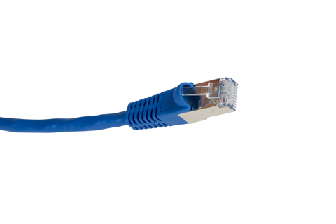
The difference between cat5 and cat6 cables lie in the methods used to manufacture them and in their capabilities. Cat5 and cat6 cables both share the same end piece, the plug that connects them to their end destination, being a patch panel or a modem. The end piece that both of these cables share is known throughout the industry as an RJ-45. These plugs can connect directly to a computer ethernet jack or router, and have been an industry standard for years.
The speed of a cat5 cable can handle up to 10/100 Mbps (megabytes per second) at 100 Mhz bandwidth, a speed that was quite efficient in earlier applications of the cat5. Cat5E cables were introduced about 15 years ago, and could handle up to 10 times the speed and bandwidth of its predecessor, the cat5. Cat6 cables have been around only a few years less than cat5e cables, and are more robust and thick. Cat6 cables support more industrialized installations and can withstand harsher conditions and also further reduce crosstalk.
If you want to discuss the difference between cat5 and cat6 cables, and how they can improve your workflow in your recording studio, drop us a line at +1 (818) 500-8142 or email us at marketing@bittree.com
We love to talk patch panels!
Patch Cord
Patch cord, also called a patch cable, is the standard electrical and optical cord used in connecting electrical and optical devices together for the purpose of routing signal from one unit to another. Often found in computer networks, television and film broadcasting and commercial and home recording studios, the patch cord is the way it all comes together.

Manufactured in a wide variety of styles from ¼” mono instrument cords, color coded patch cord pairs, XLR microphone cords to headphone extension lines, patch cords are often made of coaxial cables, with signal carried through a shielded core, with the earthed ground connected through a wire mesh surrounding the core. The end of each cord is attached to a connector, allowing the devices to be plugged into one another. The type of connector can vary widely, with different types of adaptors and sizes.
A patch cord can vary in length, ranging anywhere from straight end to end connections used to merge guitar multi-effects together, to upwards of 100’ in length for connecting power amps to their respective speaker outputs in large concert settings. A patch cord is the ability by which sound travels from an electric guitar to an amplifier, or from a drum machine to a patch bay, connecting multiple signal routing options together in one centralized hub.
The ability to make your own patch cord is very convenient and cost effective, and can add to the customization of your home studio setup. Being able to create custom lengths of patch cords can aid in the wiring of custom guitar effects pedalboards, keeping connections tidy. This is also a huge benefit in creating the perfect patch bay, with matching cord colors aiding in the organization of hardware setup and signal flow.
Patch cords can also be grouped together to create what is referred to as a “snake” in studio terms. A snake is a group of patch cords bundled together in one complete hose-like cord, with patch bays connected at either end to facilitate the connecting of devices.
If you want to discuss how good patch cords can improve your workflow in your recording studio, drop us a line at +1 (818) 500-8142 or email us at marketing@bittree.com
We love to talk patch panels!
Patch Cords, or patch cables as they are also known, are electrical or optical cables used to connect or patch together one or more electrical or optical units for routing signal. There are a multitude of electrical or optical components that utilize patch cords for connection - a switch connected to a computer, a switch connected to a router, or a vast array of musical instruments and accessories all get their signal flow from the use of patch cords.

Patch cords come in a number of different lengths, colors, and connections. In an audio studio setting, patch cords usually are found as color-coordinated pairs, implemented by the use of a patch bay or patch panel, to route signal to and from hardware devices and analog instruments. Different types of patch cords include microphone cords, headphone extension cords, XLR cords, TTL (tiny telephone lines), RCA, and ¼” TRS phone cords. Patch cords however, are typically referred to only in context of using the cords with a patch bay or patch panel.
Patch cords come in different lengths, varying from being connected end to end for instrumental multi-effect connections, or cords up to 100’ used in audio and theatrical productions to transfer sound from power amps to their respective speaker sets. In audio productions, analog ¼” patch cords are used to connect electric guitars, basses, drum machines, and synthesizers to patch bays for signal routing, or for connecting directly to a DAW for audio recording.
The ability to make custom patch cords is a huge benefit to the home studio enthusiast. With a little time and patience, it is very easy to create your own cords, and one can end up saving a significant amount of money in the long run. In creating your own patch cords, you have the benefit of creating a cleaner studio environment, because you can customize your lengths so that there is no excess cord taking up floor space or cluttering up your racks.
If you want to discuss how good patch cords can improve your workflow in your recording studio, drop us a line at +1 (818) 500-8142 or email us at marketing@bittree.com
We love to talk patchbays!